A circuit that works on a bench is not yet a product. The moment it needs to survive shipping, fit in a customer’s hand, pass basic safety expectations, and be assembled repeatedly, the housing becomes part of the engineering. This electronics enclosure design guide explains how inventors and product teams can make enclosure decisions that support a functional prototype and a credible path to manufacturing.
The enclosure is not packaging added at the end. It affects heat, wireless performance, assembly time, serviceability, user experience, cost, and even the design evidence available for a patent filing. Treating it as an early engineering decision prevents the common and expensive cycle of redesigning a PCB because the board, battery, ports, or fasteners do not fit.
Start With the Product Requirements, Not the Box
Before choosing a material or drawing a shape, define what the enclosure must do. A handheld consumer device has different priorities from a wall-mounted controller, an outdoor sensor, or an industrial test tool. The right answer depends on where the product will live, who will use it, and what failure would look like.
Start by documenting the product’s physical constraints: overall target size, battery volume, display and control locations, cable exits, mounting method, anticipated drops, operating temperature, and exposure to dust or moisture. Add the realities of production, including expected annual volume, target selling price, and whether the device may need to be opened for battery replacement or repair.
This requirement list should also account for the components people often forget until late in development. USB connectors need insertion clearance. Switches and buttons need travel. Antennas need protected space and material that does not interfere with their signal. LEDs need light pipes or clear windows if they are buried behind an outer wall. Each one changes the enclosure geometry.
Build From the Inside Out
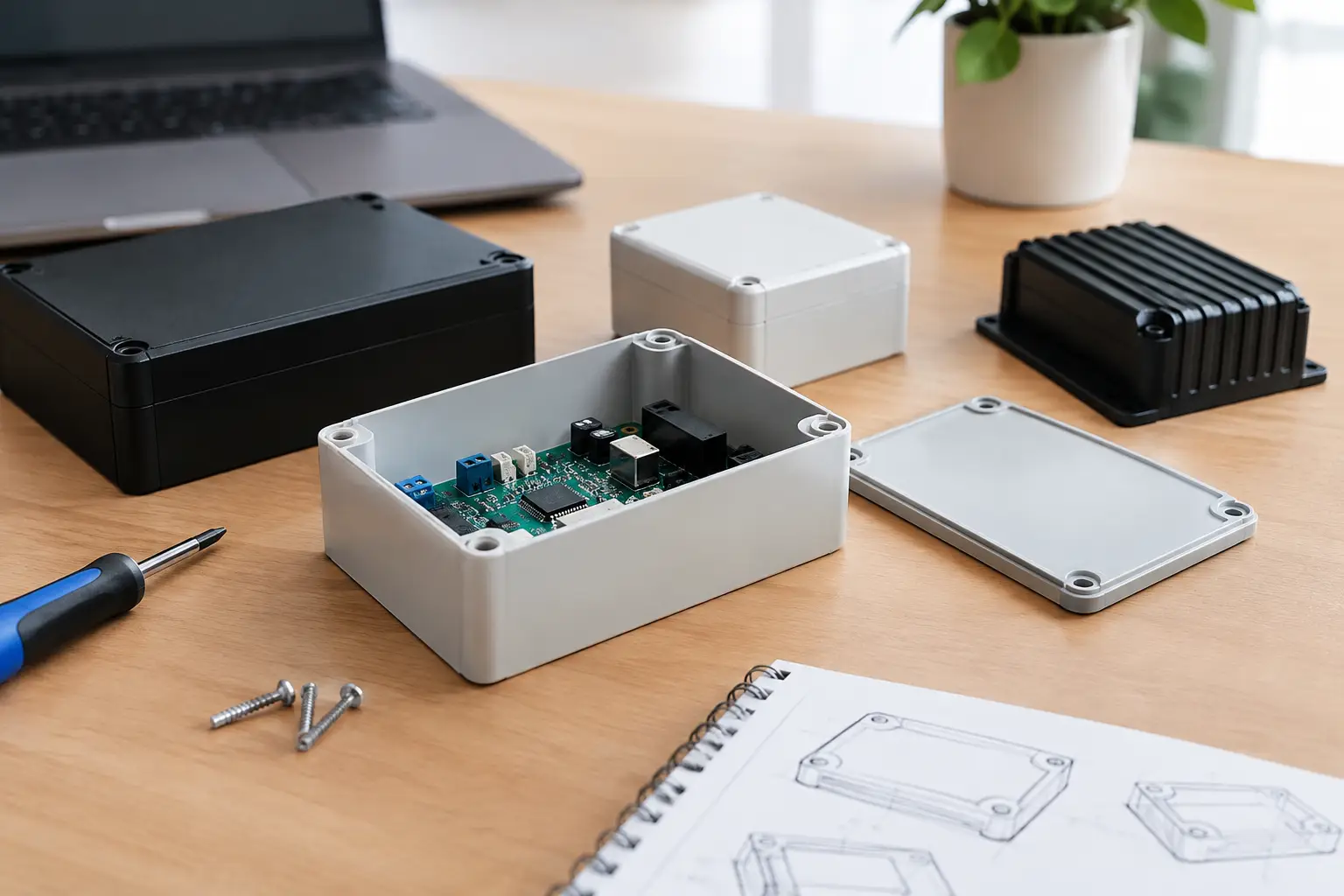
A practical enclosure begins with the internal architecture. Place the PCB, battery, display, speakers, motors, sensors, connectors, and any moving parts first. Then create a controlled amount of clearance around them for assembly, wiring, thermal movement, and manufacturing variation.
Do not design to nominal dimensions alone. Real components have tolerances, and printed circuit boards, molded parts, and machined parts all vary slightly. A connector that appears to align perfectly in CAD can be difficult to plug in if its opening is too tight or shifted by a fraction of an inch. The same is true of batteries that swell slightly over their service life or cable assemblies that bend less sharply than expected.
A good design uses intentional locating features rather than allowing the board to float inside the case. Standoffs, ribs, retention clips, and screw bosses can position components reliably. However, these features must be sized for the manufacturing process. A wall that looks acceptable in a 3D print may create sink marks, warping, or weak sections in an injection-molded part.
Plan for assembly at the same time
Ask a simple question: can someone build this device in a repeatable sequence without force, guesswork, or special handling? If the answer is no, the enclosure needs more development.
Assembly-friendly designs provide a clear order of operations. The board drops into defined supports, wires route through dedicated channels, screws are accessible, and the final cover closes without pinching anything. For a prototype, hand assembly may be acceptable. For a product intended for larger production runs, every extra screw, adhesive step, or difficult cable connection adds cost and quality risk.
Choose Materials Based on Use, Not Appearance Alone
Material selection is one of the most visible enclosure decisions, but appearance is only part of the calculation. Plastic is often the right choice for consumer products because it can be lightweight, economical at scale, electrically insulating, and easy to shape. ABS, polycarbonate, nylon, and PC-ABS blends all have different strengths involving impact resistance, stiffness, heat performance, and finish.
Metal can provide a premium feel, structural strength, heat dissipation, and electromagnetic shielding. It can also increase machining cost, add weight, and create problems for antennas and wireless communication. A metal enclosure may require a deliberate antenna window or a nonmetallic section so Bluetooth, Wi-Fi, cellular, GPS, or other radio signals can function correctly.
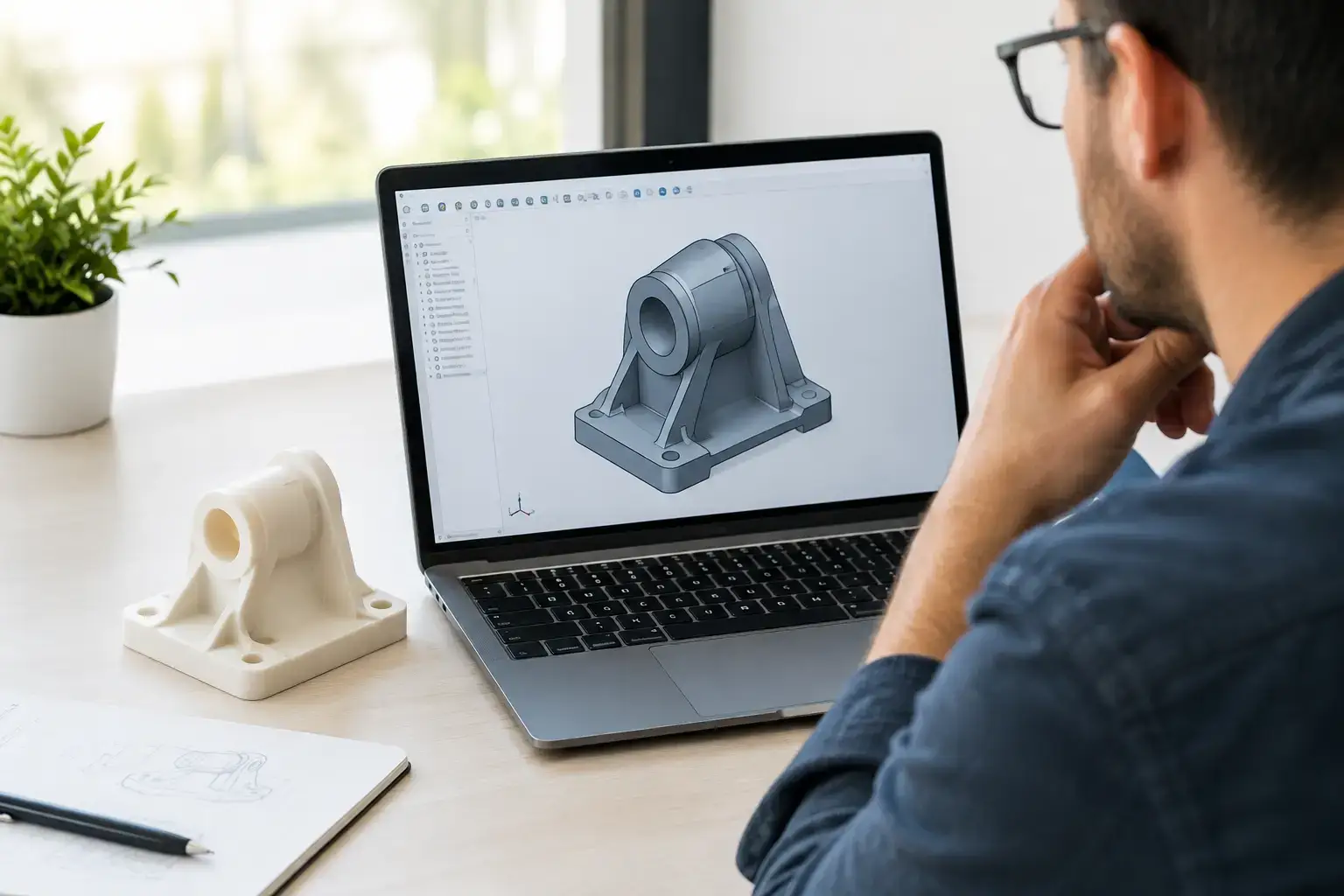
For early prototypes, 3D-printed materials are valuable because they allow speed and iteration. They are not automatically representative of final production material. Printed parts can have visible layer lines, different strength by direction, lower heat resistance, and less predictable sealing performance. Use them to test fit, ergonomics, and assembly, then confirm critical behavior in production-intent materials when the project advances.
Design for Heat, Electronics, and Signal Integrity
Heat has no interest in your preferred industrial design. If power components, processors, LEDs, batteries, or chargers generate heat, the enclosure must give it a path out or reduce the load being trapped inside.
Vents can help, but they affect dust and water resistance. Metal surfaces can act as heat spreaders, but they may require thermal pads and careful electrical isolation. In some products, a larger internal air volume is enough. In others, the real solution is to change component placement, reduce power consumption, or select a different processor or power architecture.
Electromagnetic interference is another design issue that should be considered early. Sensitive electronics may need shielding, grounding strategy, separation between noisy and low-level signals, or conductive coatings. The enclosure and PCB design should be coordinated, especially for wireless products. An antenna placed too close to a battery, display, metal bracket, or shield can lose range even if the electronics otherwise work correctly.
Make the Human Interaction Obvious
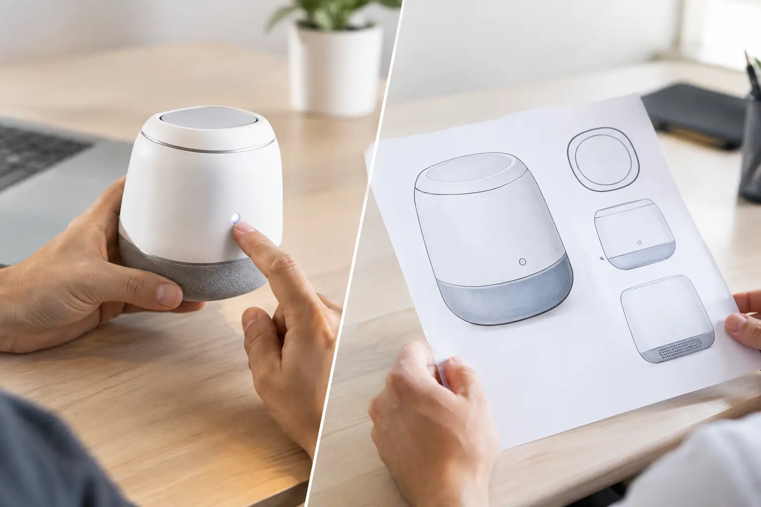
Customers judge a product before they understand its engineering. The way a button feels, the location of a charging port, the angle of a display, and the grip of the housing all communicate quality.
Controls should be reachable without accidental activation. Labels should be readable in expected lighting. Ports should be easy to identify and use with common cables. If a user wears gloves, has limited dexterity, or uses the product in a garage, kitchen, workshop, or outdoors, design for that reality rather than an ideal desktop scenario.
Ergonomic evaluation is where rapid prototypes earn their value. Hold the enclosure. Try to operate it one-handed. Put it in a pocket, mount it to a surface, connect every cable, and simulate normal use. A CAD rendering can look polished while hiding a sharp edge, awkward seam, poor center of gravity, or button placement that frustrates users.
Decide How the Enclosure Will Be Manufactured
The design process changes when the manufacturing process changes. CNC machining supports strong prototype parts and lower-volume production, but complex geometry can increase cycle time and cost. Sheet metal works well for many industrial products but introduces bend radii, exposed edges, and limits on complex forms. Injection molding has excellent potential for repeatability and per-unit economics at higher volumes, but it requires upfront tooling investment and careful attention to draft angles, wall thickness, ribs, undercuts, and parting lines.
There is no universal best process. A startup validating demand may benefit from a lower-cost prototype route before committing to production tooling. A company with established sales volume may justify a molded enclosure sooner because assembly consistency and unit cost matter more. The critical point is to avoid designing a part for one process and assuming it can be transferred to another without changes.
Protect the Details That Make the Product Different
For inventors, the enclosure may carry more intellectual property value than expected. A distinctive mounting mechanism, a new arrangement of electronic elements, an ergonomic feature, or a functional interface can all be relevant to how the product is documented and protected.
Keep dated development records, CAD revisions, prototype photographs, and notes explaining why key features exist. These materials can support both engineering decisions and patent-oriented development strategy. A proof-of-concept prototype does not have to be production-ready, but it should demonstrate the features that make the invention work and make it different.
Industry of Concepts helps clients connect enclosure development with industrial design, electro-mechanical engineering, prototyping, manufacturing preparation, and patent support. That connection matters because a product is easier to protect and commercialize when its physical design is developed with purpose rather than as an afterthought.
Test Before You Commit
A finished-looking enclosure is not automatically a validated enclosure. Test the conditions that matter for the product: repeated button presses, connector insertion, basic drop events, mounting loads, charging cycles, temperature exposure, and transport. If the product claims water or dust resistance, test the seals and openings instead of assuming they will perform.
Early failures are useful information. A cracked screw boss may point to a material problem, a wall-thickness problem, or an assembly torque problem. A loose port may reveal an internal support issue. Treat each failure as a design input, then revise before investing in expensive tooling or committing to a production order.
The strongest enclosure designs make the technology feel simple, trustworthy, and ready to use. Begin early, prototype honestly, and let every fit check and test move the invention closer to a product people can confidently buy.