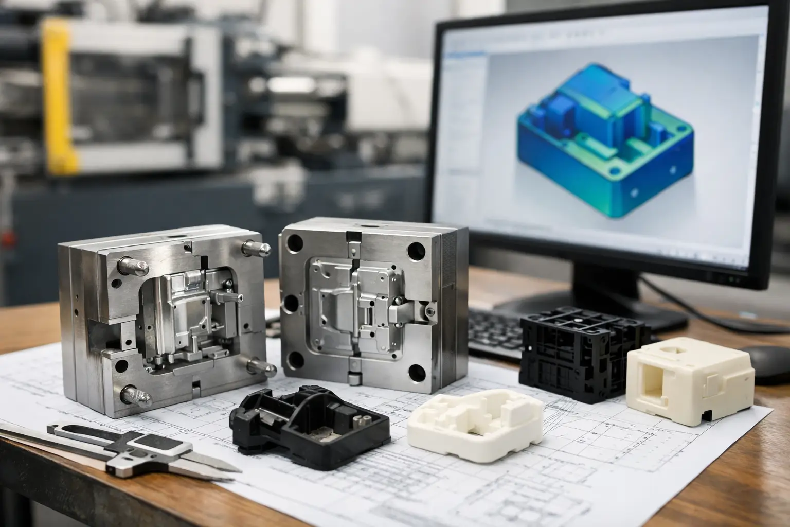
A molded plastic part can look simple on a screen and become very expensive the moment it reaches tooling. That is why a sound injection molding design guide starts before the mold is quoted. The decisions behind a housing, cap, clip, enclosure, or consumer product component determine whether it fills consistently, releases cleanly, holds its shape, and can be made at a cost that supports the business.
For inventors and startup teams, the goal is not to become mold makers overnight. The goal is to make informed product decisions early, when changing a CAD model is far less costly than modifying hardened steel. Good design for manufacturing protects both your development budget and your path to market.
Start With What the Part Must Do
Injection molding is a manufacturing process, not a material choice or a styling exercise. Begin by defining the job of the part. Does it carry a load, protect electronics, snap onto another component, contact food, survive UV exposure, or need a premium cosmetic surface? Those requirements drive the material, geometry, finish, and mold strategy.
A phone accessory enclosure and a garage-mounted electrical housing may both be plastic shells, but they face entirely different conditions. One may prioritize appearance and tactile feel. The other may require flame resistance, impact strength, environmental durability, and tight fit around internal components. Treating them the same creates avoidable design problems.
This is also where commercial realities belong in the conversation. Expected production volume, target unit cost, assembly method, packaging, and market position all affect the right solution. A complex feature may be justified for a high-margin product with substantial volume. For an early launch or a limited run, a simpler part can be the smarter investment.
Injection Molding Design Guide: Build for Flow and Release
Molten plastic must travel through the mold, fill the cavity, pack out correctly, cool, and then release without damaging the part. Every major design rule traces back to those physical steps.
Use consistent wall thickness whenever possible
Uniform walls are one of the most valuable habits in injection molding design. When one area is much thicker than another, the thick section cools more slowly. This can cause sink marks, internal voids, warping, and longer cycle times. Longer cycles raise the per-part cost, even when the mold performs correctly.
The ideal wall thickness depends on the resin and the part’s function. Rather than adding thick material for strength, use geometry that distributes loads efficiently. A thin wall supported by a properly designed rib can often outperform a bulky wall while molding more predictably.
There are exceptions. Some products need thicker sections for impact resistance, threaded inserts, or structural demands. When thickness changes cannot be avoided, transition gradually rather than creating an abrupt step. A gradual shift gives plastic a better path to flow and cool.
Add draft from the beginning
Draft is the slight taper applied to vertical faces so the part can release from the mold. Without enough draft, the part may drag against the mold wall, scuff cosmetic surfaces, distort during ejection, or require extra mold complexity.
A common starting point is about 1 to 2 degrees of draft, although surface texture, depth, material, and geometry can require more. Textured surfaces need greater draft because the texture increases friction as the part is ejected. Features such as deep ribs and narrow pockets deserve special attention because they are easy to overlook in a concept model.
Draft can affect appearance and fit, so it should be considered while the industrial design is still flexible. Adding it late can alter dimensions, corner relationships, and mating features throughout the product.
Design ribs and bosses with restraint
Ribs add stiffness. Bosses create attachment points for screws, inserts, or mating components. Both are useful, and both frequently cause molding defects when they are oversized.
A rib that is too thick relative to the main wall can leave a visible sink mark on the opposite side. A heavy boss can do the same. As a general design approach, keep rib and boss walls thinner than the nominal wall, use generous fillets at their base, and avoid stacking too much material in one location.
If a screw boss must withstand repeated assembly, its performance depends on more than diameter. The resin, screw type, pilot-hole design, surrounding support ribs, and expected torque all matter. Testing a representative prototype is often the right way to validate the design before committing to production tooling.
Plan the Parting Line, Gate, and Ejection Strategy
A mold must open somewhere. The line where its two halves meet is the parting line, and it affects both manufacturing and appearance. On a consumer-facing product, placing that line along a natural edge, seam, or change in surface direction can make it far less noticeable.
Plastic also needs an entry point into the cavity. This is the gate location. Gate placement influences flow direction, pressure, weld lines, cosmetic quality, and warpage. A gate hidden on the underside may improve appearance, but it may not be the best choice for filling a long, thin part. The design needs to balance both concerns.
Ejector pins push the finished part out of the mold. Their marks are usually visible to some degree, so they should be located on non-cosmetic surfaces where possible. Flat, reinforced areas are generally better ejection locations than delicate walls or highly polished display surfaces.
These mold details are not reasons to limit a product concept. They are reasons to involve manufacturing thinking while the concept is taking shape. A capable engineering team can often preserve the intended form by adjusting subtle geometry rather than forcing a major redesign later.
Avoid Undercuts Unless Their Value Is Clear
An undercut is a feature that prevents the part from being released with a simple straight-open mold. Internal snap hooks, side holes, threads, and certain latches can create undercuts. They may require slides, lifters, collapsible cores, unscrewing mechanisms, or secondary operations.
None of those solutions is automatically wrong. A side action may be essential to the product’s function. But each adds cost, tool complexity, maintenance requirements, and potential cycle-time impact. For a founder watching every development dollar, the question is simple: does this feature create enough customer value to justify its manufacturing cost?
Sometimes a product can be redesigned to eliminate the undercut. A side hole may become an open slot hidden by assembly. A molded thread may be replaced by a separate standard fastener. A single complex body may become two simpler parts that snap or screw together. The best answer depends on assembly time, product strength, aesthetics, and volume.
Choose Material Based on Use, Not Familiarity
Many products start with a vague instruction to use plastic. That is not enough. Commodity resins such as polypropylene or ABS may be excellent choices for the right application, while engineering materials such as nylon, polycarbonate, acetal, or glass-filled compounds may be necessary for heat, strength, chemical resistance, or dimensional stability.
Every material brings trade-offs. Polycarbonate can offer high impact resistance but may be more difficult to process and more vulnerable to certain chemicals. Nylon is strong and useful for mechanical parts, yet it absorbs moisture and can change dimensions. Glass-filled materials can improve stiffness but may increase wear on tooling and create a less refined surface finish.
Material shrinkage is equally significant. Plastic contracts as it cools, and each resin behaves differently. The mold is built with that shrinkage in mind, but the part designer must account for it where fit and tolerance matter. Mating components, lids, seals, gears, and electronic interfaces should be evaluated as a system rather than as isolated parts.
Set Tolerances That Match the Product
Tight tolerances sound like quality, but unnecessary precision can increase tooling difficulty, inspection demands, scrap risk, and cost. Specify precision where it serves function: a sealing surface, a bearing fit, a critical electronic interface, or a feature that controls assembly alignment.
For less critical surfaces, allow reasonable manufacturing variation. This does not mean accepting poor quality. It means directing quality effort toward the dimensions that make the product work. A clear tolerance strategy helps engineers, mold makers, and manufacturers evaluate the design against the same requirements.
Consider how the part will behave after molding as well. Heat, moisture, load, and time can affect plastic dimensions. If the product has moving parts or needs to assemble with metal hardware, tolerance planning must reflect real operating conditions, not only nominal CAD dimensions.
Prototype Before You Cut Steel
A 3D-printed prototype is valuable for proving size, ergonomics, assembly sequence, and the basic user experience. It is not always a reliable substitute for an injection-molded part. Printed materials, layer orientation, surface quality, and mechanical behavior can differ significantly from production resin.
The right development path often includes more than one prototype. Early models can test the concept and support patent-oriented documentation. Functional prototypes can validate mechanisms, electronics, and assembly. Pre-production samples can then confirm the design in the intended resin and process.
This staged approach gives inventors better control. You can discover whether a snap feature is too stiff, whether a wall flexes under load, or whether an enclosure traps heat before tooling costs narrow your options. Industry of Concepts helps product teams connect those prototype lessons to practical manufacturing decisions.
Keep the Tooling Conversation Open
A mold quote should not be treated as the first manufacturing review. Before approving tooling, review the latest CAD with the people responsible for engineering, mold design, and production. Confirm the material, finish, gate approach, parting line, draft, shrinkage assumptions, critical dimensions, and expected annual volume.
Ask what could fail in production, not just whether the mold can be built. Can the part warp? Will the cosmetic face show weld lines? Is there a likely sink mark near a boss? Does the assembly require a fixture? Can the tool be maintained economically if production grows?
A thoughtful injection-molded product is not defined by having the fewest features. It is defined by making each feature earn its place. Build the part around its real purpose, test what matters, and make manufacturing decisions while you still have room to improve them. That is how an idea becomes a product worth protecting, producing, and selling.